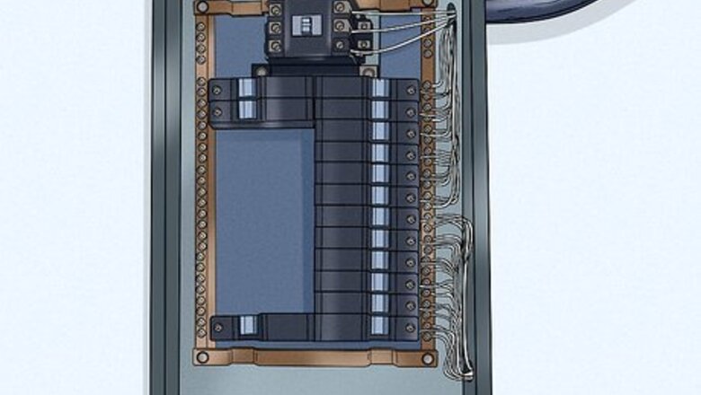
views
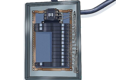
Determine the maximum power that will be drawn on the new circuit. Divide the total number of watts by 120 (or 240 for a 240-Volt circuit). The result is the maximum current, in amperes (amps), for the circuit.
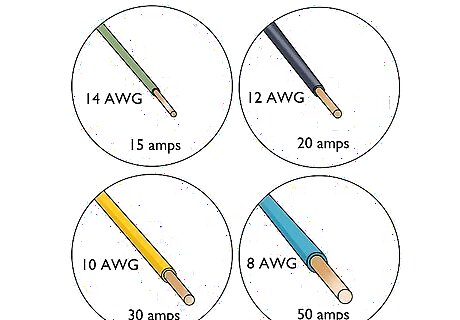
Select the proper gauge conductor for the maximum current of the circuit. Select a 14 AWG conductor for a maximum current up to 15 amps. Select a 12 AWG conductor for a maximum current up to 20 amps. Select a 10 AWG conductor for a maximum current up to 30 amps. Select an 8 AWG conductor for a maximum current up to 50 amps.
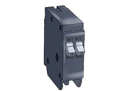
Purchase the correct circuit breaker. You must use a circuit breaker that is approved for use in your service panel. In most cases, you must use a circuit breaker made by the same manufacturer as that of the service panel. Select a circuit breaker with a current rating that does not exceed the rating of the circuit. For example, if a circuit is wired with a 12 AWG conductor, only use a circuit breaker rated for 20 amps or less.
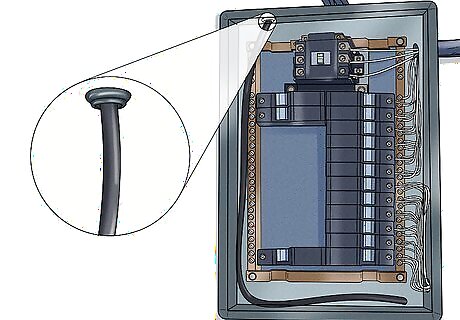
Run the electrical cable for the new circuit. Allow for sufficient cable at the service panel to route the cable to the entry point in the box and then from that point to the farthest destination in box. As a rule of thumb, allow for a length of cable that is 2 to 3 times the height of the box.
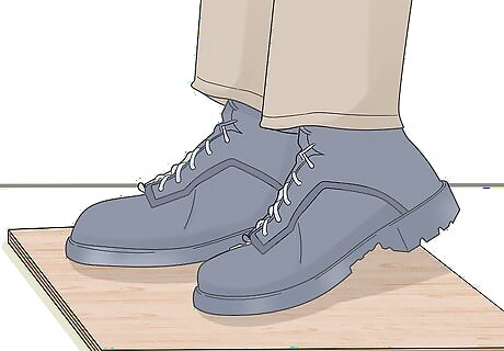
Place a rubber mat or sheet of plywood (or other dry wood) in front of the service panel and stand on it while working in the panel. Do not work alone when a breaker panel cover is removed. You may need someone to rescue you or to call for help.
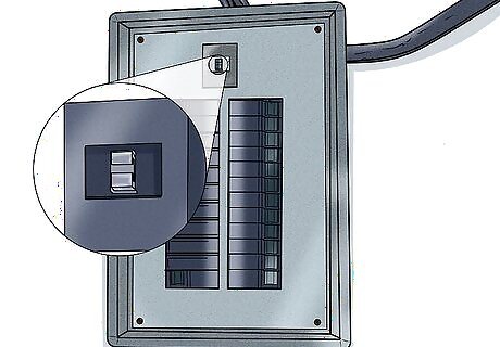
Open the cover of the service panel and turn off the main breaker.
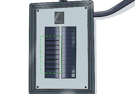
Note the location of unused circuit breaker spaces in the service panel cover. You must install the new circuit breaker to line up with a pre-punched knockout in the cover.
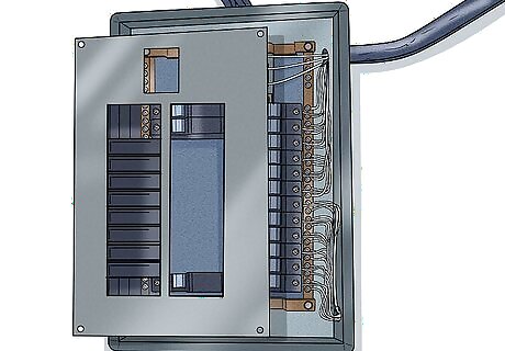
Remove the service panel cover. Warning: The power supply terminals that supply the main switch will still have live voltage on them, even if the main switch is turned off. Use extreme caution.
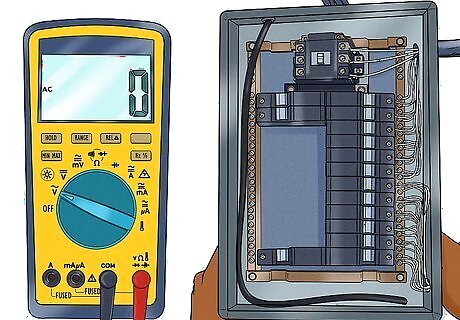
Measure the voltage to verify that the power is off in the service panel. Place one probe of a voltmeter on the neutral bus bar and place the other probe on the supply bus bar (the bus bar to which the existing circuit breakers are attached). If the voltmeter does not read 0, the power in the service panel is not off and you should not proceed.
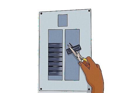
Choose the location in the service panel for the new circuit breaker. Remove the knockout. Use a hammer and screwdriver to bend the knockout. Grasp the edge of the knockout with pliers and bend it back and forth until it breaks loose.
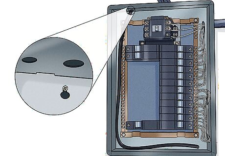
Locate a circular knockout on the top, side or bottom of the service panel box that is convenient for entry of the new circuit cable and for routing conductors inside the box to the new circuit breaker location. For safety reasons, select a knockout that is not in close proximity to the live service wires that connect to the main circuit breaker. Remove the knockout.
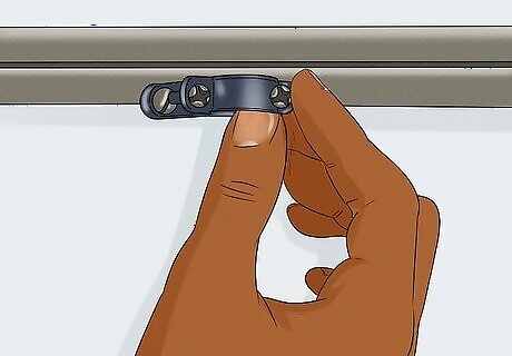
Install a cable clamp in the circular hole in the service panel box with the clamp on the outside of the box. Use a screwdriver to open the clamp as far as possible. The cable clamp must be selected properly for the size and type of cable you are using.
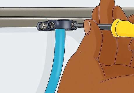
Route the cable to the new cable clamp.
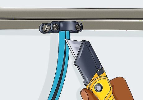
Identify the location on the cable that will extend approximately 1 inch (2.5 cm) inside the cable clamp. Split and strip off the outer jacket of the cable from this point to the end of the cable. Use a utility knife to carefully cut down the middle of the cable jacket. Peel the jacket apart and pull it off the conductors back to the identified point where you began your cut. Cut the jacket off with a utility knife. Remove the paper that surrounds the bare copper ground wire.
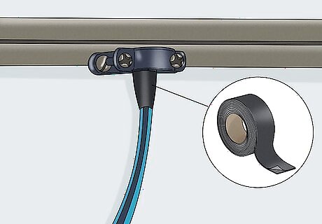
Wrap electrical tape around the ends of the conductors to hold them together. Route the conductors through the cable clamp until 1 inch (2.5 cm) of the jacketed cable extends through the cable clamp. Tighten the cable clamp. Remove the electrical tape holding the conductor ends together.
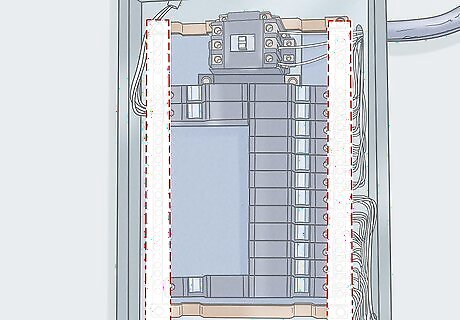
Determine whether your service panel has separate neutral and ground bus bars. Your service panel has separate neutral and ground bus bars if all of the white wires are routed to one bus bar and all of the bare (or green) ground wires are routed to another bus bar. Your service panel does not have separate neutral and ground bus bars if the white and ground conductors are connected to only 1 bus bar. If you are installing a GFCI or AFCI type breaker, the white neutral wire is also routed to a separate terminal on the breaker.
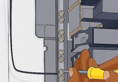
Route the ground conductor to the ground bus bar (or common neutral bus bar, as applicable). Cut off any excess conductor with the wire cutter. Loosen a screw in the bus bar, insert the conductor through the hole and firmly tighten the screw.
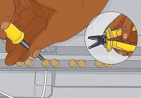
Route the white wire to the neutral bus bar. Cut off any excess conductor. Use a wire stripper to remove approximately 1/2 inch (1.3 cm) of insulation from the end of the conductor. Loosen a screw in the bus bar, insert the wire in the hole under the screw and firmly tighten the screw.
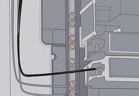
Determine how you will route the black wire to the location for the new circuit breaker. Cut off any excess conductor. Strip approximately 1/2 inch (1.3 cm) of insulation from the end of the conductor. Loosen the screw on the circuit breaker and insert the end of the black wire under it and then firmly tighten the screw. If you are installing a double-pole breaker for a 240-Volt circuit, connect the black wire to either screw connector on the circuit breaker and connect the red wire to the other screw connector. If you are installing a GFCI or AFCI type of breaker, attach the branch neutral to the correct terminal on the breaker and attach the white coiled neutral wired from the breaker to the neutral bar.
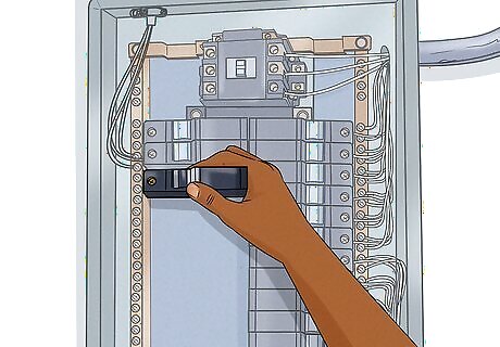
Install the circuit breaker. Set the new breaker switch to the off position. Route the black wire that is connected to the breaker switch from the cable clamp to the location where you will install the breaker. Hold the circuit breaker at an angle and align its connection point with the rail, clip or slot in the service panel. Press the other end of the circuit breaker into place. Some brands will click into place; others will not. To assure that the breaker is properly installed, verify that it is level with the adjacent circuit breakers.
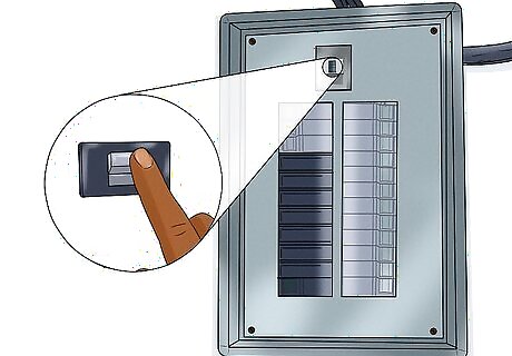
Test your installation by first turning on the main breaker in the service panel and then turning on the new circuit breaker. Use a circuit tester or plug in an electrical appliance to test the new circuit.
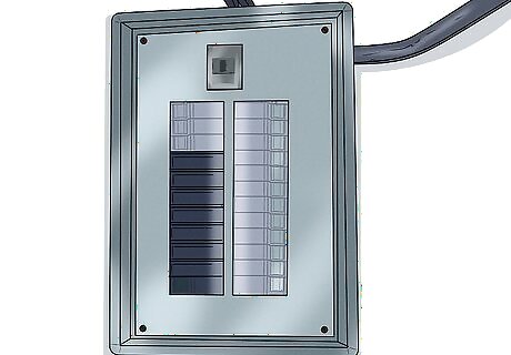
Replace the breaker panel cover. Be sure to add a new label to the cover that indicates the circuit fed from the new breaker.


Comments
0 comment