views
X
Research source
This project will help you build a simple sheet metal brake for bending small work for those who prefer to do it yourself.
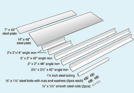
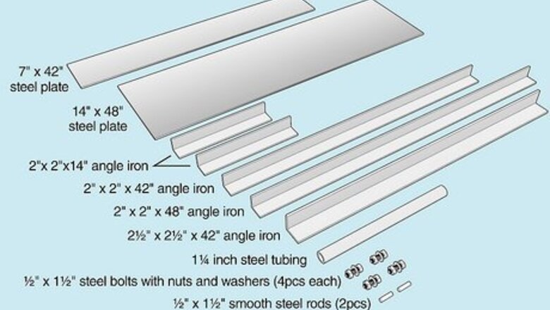
Select materials that will be strong enough for your needs. ⁄4 inch (0.6 cm) steel plate with bracing will enable you to bend 14 gauge galvanized steel sheet metal in lengths up to about 3 feet (0.9 m), which is the size and specification for the project described in this article. Here are some materials used to build this particular brake. 1/4 cold rolled steel plate, one piece 7"X42", one 14"X48" 1/4"X2" angle iron, two pieces 14", one piece 42", one piece 48" 5/16"X2 1/2" angle iron 42" long 1 ⁄4 inch (0.6 cm) steel tubing, about 18" long 1/2"X1 1/2" steel bolts with nuts and washers, 4 each. 1/2"X1 1/2" smooth steel rods, 2 required
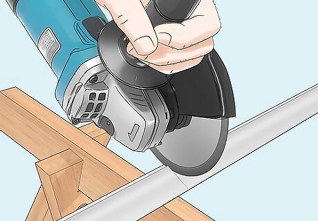
Cut the angle iron and steel plate in sizes listed above, making sure edges are square and straight. Lay the 14" wide plate on saw horses or a workbench so the remaining pieces can be fitted.
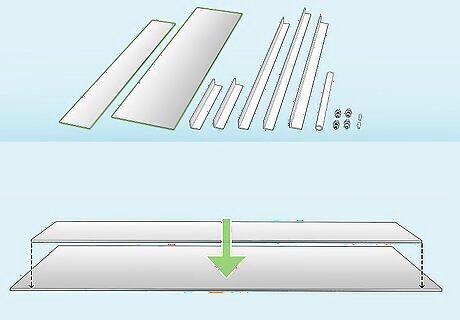
Lay the 7"X42" piece on top of the 14" piece with the front edges flush, and an equal space on each end. Clamp these if desire to prevent them from shifting during the next steps.
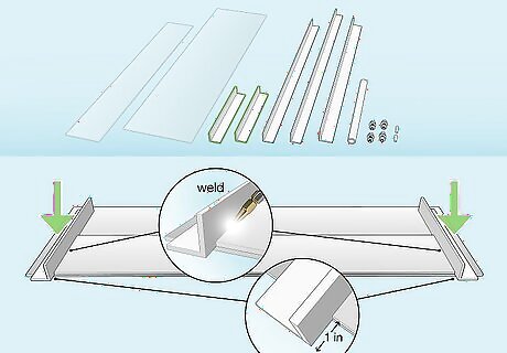
Align one of the 14" angles on each end of the 7" wide (top) piece of plate so it overhangs the front edge about 1 inch (2.5 cm), and weld them to the 7" wide plate. These will act as the clamping hinges when the brake is assembled.
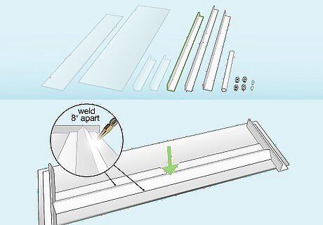
Lay the 42" piece of 2" angle iron on top of the 7" wide (top) plate, centering it between the two end angles in the center of the sheet with the angle up, and weld it in place, with at least one inch welds on each edge 8 inches (20.3 cm) apart. This will stiffen the plate when a piece of metal is clamped in the brake.
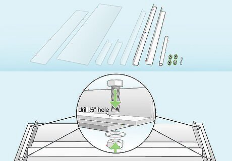
Drill 1/2 holes in the flats of the two 14 inch (35.6 cm) angles, one near the front edge of the 14" wide plate, and one near the back edge. The location of these bolts isn't critical, but it will look better if they are in line with each other and on each end. Install one of your ⁄2 inch (1.3 cm) bolts into each hole, bolting the angle to the plate loosely.
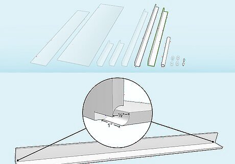
Notch the angle point of each end of the 2 ⁄2 inch (1.3 cm) angle ⁄2 inch (1.3 cm) wide and 1 inch (2.5 cm) deep for the hinge pins to fit into. The exact location of these will be determined by the alignment of the brake, as you will find later, but you should be able to center your 1/2 rods in the center of the corner of the angle.
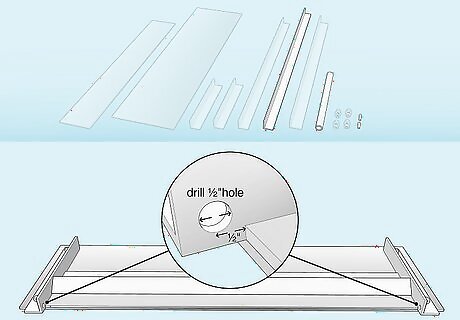
Drill ⁄2 inch (1.3 cm) holes ⁄2 inch (1.3 cm) beyond the front edges of the 7" plate through the 14"X2" angles where they overhang the front of the plate just above the bottom flange of the angle iron. These are the sockets the hinge pins will fit into.
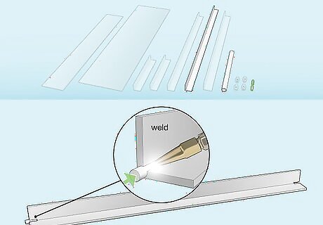
Weld one of the smooth 1/2 rods into one of the notches you cut into the 2 1/2" angles, it should extend 3/4" (or more) beyond the end of the angle. Keep it as straight as possible to the corner of the angle iron so it can swivel freely when it is installed.
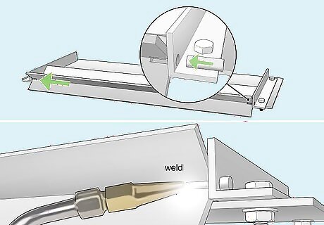
Fit the pin (1/2 smooth rod) you just welded onto the angle into the socket you drilled earlier, then line the other notch up with the socket on the opposite end so you can fit the other pin into place, then weld that pin to the angle iron.
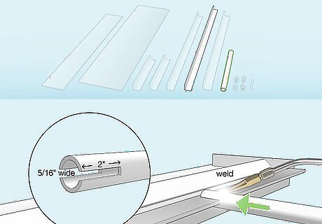
Notch the steel pipe 5/16" wide by 2" deep so it will slide over the top angle to create a handle to operate the braking angle you just installed. Center it on that angle, and weld it into position.
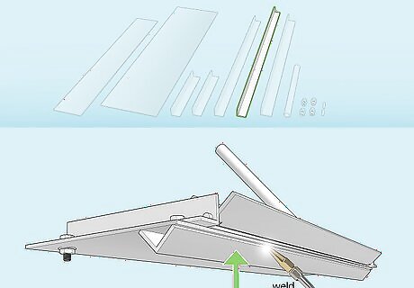
Turn the brake over (it will be heavy) and place the 1 1/2" X 48" angle near the front edge of the 14" wideX48" piece of steel plate and weld it the same as the upper stiffener.
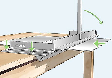
Mount the brake on saw horse or your workbench with a few inches hanging over to allow the brake and slide a piece of sheet metal between the 7" and 14" plate, snug the bolts down to clamp it, and pull the pipe handle towards you to bend the metal.


Comments
0 comment